State Machine Diagrams
For the traffic light above we described actually a state machine. Since taking photos of real objects is cumbersome, and we also want to describe abstract things we cannot take a photo off, we replace the photos above with a more convenient symbol, a rectangle with rounded corners. These are the states in which the traffic light can be. A state machine for the traffic light looks hence like this:

Have a look at the detailed elements in this diagram:
- The frame has a five-cornered compartment at the top, showing the name of the state machine, prefixed with the keyword
stm. - The states are shown as rounded rectangles. The state names are shown in bold text. As a naming convention, we only use lowercase letters, numbers, and underscores for state machine names, similar to rules for variable names in programming languages.
- The start of the state machine is shown by a compact black dot. This is also a state, called the initial state. Once the state machine is activated, it leaves this initial state.
States
State symbols with the same name refer to the same state. This means, we can use a copy of the state symbol to make our layout easier, without changing what we actually mean by the diagram. For instance, we can remove the long arrow from state yellow to state red just by having another copy of the symbol for state red:

The diagram describes exactly the same behavior. Both state symbols for the state red refer to the same state, so our traffic light still has the same number of states, just its layout changed. In this simple state machine this doesn't really matter, but this can help you to create better layouts once state machines become larger.
State Names: Selecting good names for states can help making state machine easier to understand, especially when the states map to phases of the thing we want to model, like on and off for a lamp, or open and close for a lock. However, sometimes there is no obvious good name. In such cases, I recommend to use state names like s0, s1,..., which can make life easier. You always have the possibility to attach a note to a state and explain what it means.
Pay attention to the state symbol. It's a rectangle with some rounded corners, nothing else!

Transitions
The arrows between the states are called transitions. We have said above that the state machine is at any point in time in exactly one of its states. It is not in two or more of them at the same time, and it is never somewhere in between. Conceptually, this means that a state machine switches from one state to another within no time at all, meaning that transitions take no time. This sounds magical, but we will come back to this.
So far, we have not yet talked about when a transition happens, this means, what triggers a transition. We have, for example, not described when the traffic light switches from red to red_yellow. There are three types of events that can trigger transitions in a state machine:
- The state machine is started, then its transition from the initial state is triggered. This happens when the component or code surrounding the machine is started and then starts up the machine, for instance when we boot our firmware and the software starts running.
- The state machine observes the expiration of a timer. Timers are managed by the machine itself, and we will learn how timers can be started and stopped later.
- The state machine receives a message. State machines can receive messages from other parts of the system, which can be code, drivers, interrupts or communication modules, or other state machines.
A transition must have exactly one trigger. Without one, it would never be started at all. For simplicity, we also don't allow more than one trigger. A trigger is declared using a label on the arrow, followed by a /. This means that you should have a trigger label at all transitions, with the only exception being transitions starting at initial states, because their trigger is implicitly the start of the entire machine.
Actions
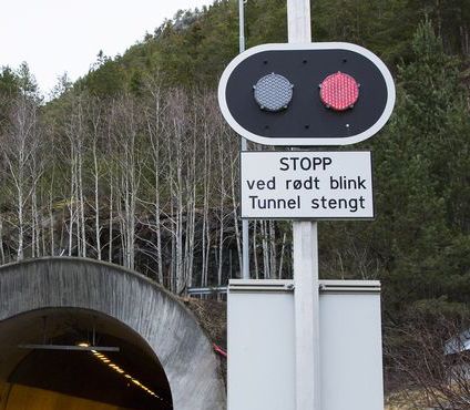
Let's have a look at a blinking light that you find often at the entry of tunnels. The light blinks with two lamps to indicate that the tunnel is closed. The blinking happens so that either the left lamp or the right lamp are on, and they switch every second.
From our experience with the more complex traffic light, this should be an easy state machine to write down. It has two states, leftand right, corresponding to one of the lamps being switched on. We also added labels to some of the transitions. They describe that the state machine switches from state left to state right triggered by an event t1. This is a timer. It switches back with a timer t2. The detailed timer operations are not yet visible, we come later to that. In this blinking light we also show how to switch it off. This happens by an event called off, and it can happen in any of the two states.

We also want to specify the actions to switch the individual lamps on and off. We assume that we have for this the actions left_on(), left_off(), and right_on(), right_off(). We already use Python syntax for these actions. In our state machine diagram we can use these actions and add them to the transitions.
The actions are also called an effect of the transition, and happen at the same instant the transition is executed, that means, when we switch states. The effects are written behind the / of the transition label.
- The state machine runs action
left_on()when it starts, as declared by the initial transition. - When the machine switches from state
lefttoright, it runs actionsleft_off()andright_on(), separated with a;. - When the machine switches from state
righttoleft, it runs actionsright_off()andleft_on(), separated with a;. - When the blinking light switches off and moves into the final state, we run actions
left_off()orright_off(), depending on in which of the two states we are.

Another way to execute actions is to add them to a state, and run them when we enter or exit the state. For some problems, such as the blinking light, this makes the diagram much nicer. Have a look at the functionally equivalent diagram:

Here we have drawn the state symbol with a compartment and add entry and exit actions to it. Actions that are preceded with the prefix entry/ are executed when the state machine enters the state, and actions preceded with the prefix exit/ run when the machine exits the state. In the example this cleans up the entire diagram, since we also can remove the actions from the initial transition and the transitions that target the final states. When we before had to add actions to all transitions entering or exiting a state, it is now enough to only declare them once within the state.
You can list as many entry and exit actions for a state as you need, just add a new line with the prefix entry/ or exit/ for each of them. And of course, it looks nice when you list all entry actions above the exit actions.
We also assume that they are executed in the way they are sorted, that means when we enter a state then the entry actions are executed in the order they are written, and the same for the exit actions when we exit the state.

Mind the Slash! The slash on the transition labels separates the triggers from the actions.
- For initial transitions (the ones originating at an initial state) that do not have an action, the label is empty.
- For initial transitions with actions, we add the slash before the actions:
/a1(); a2() - For actions that do not start at the initial state, they need to declare exactly one trigger, followed by the slash. Optionally, they can declare actions as they need. For instance
t1/ort1/a1(); a2().
Timers
The expiration of a timer can trigger a transition. By convention, we name timers with a prefix t, like for example t0. To declare that a transition is triggered by a timer, we simply write the name of the timer in the beginning of the transition label.
State machines manage timers on their own, wich also means that timers can only be started as part of an action within the same state machine. As we anticipate already our implementation in Python, we use the following syntax for controlling timers:
start(t1, 1000)starts a timer with namet1that will expire after 1000 milliseconds. If we invoke this action again while the timer is active and has not yet expired yet, the countdown will again start from the beginning, i.e., we expect the timeout 1000 milliseconds from the last call ofstart(t1, 1000).stop(t1)stops a timer, so that a timeout will not happen in the future. In case this action is called butt1already expired or was never started before, nothing happens.
Spaghetti Timer Example
Imagine we want to describe the behavior of a simple spaghetti timer. This timer expires after 10 minutes and then beeps for 3 seconds. We can do this with the state machine below.

Using entry and exit action on the states, we can also write this one in a more compact form.

Exercise: Simulate both of these state machines in you head or on paper by going through all the states, starting with the initial state. Verify that these two versions really are functionally equivalent.
Internal Transitions
You have seen that we can declare entry and exit actions within a state symbol, which lets us in some cases describe more compact state machines. Another thing we can declare within a state is an internal transition. The internal transition has a label like normal transitions, trigger/actions but is written inside the state symbol, between the entry and exit actions.

The state s1 above declares an internal transition A/a_2(). It is triggered when the event A is happening. When that happens, action a_2() is executed. Because it is an internal transition, the entry and exit actions are not executed. Also, because the state stays the same, we can react many times to the event A. Whenever it occurs and we are in state s1, action a_2() will be executed.
Note: When you look at the entry and exit actions, you see that they almost look the same as an internal transition. And the notation is quite consistent, because the prefix entry and exit before the / really do describe when the action behind the slash is executed. But these are not transitions, just declarations of entry and exit actions.
Choice States
In some cases, we want to have a choice in which state a transition should switch, based on conditions in data. As an example, let's look at the incomplete state machine below. It describes a part of a controller for a heater. In state heater_on we wait for 1 second for timer t, which triggers the transition towards the choice state. This choice state has two alternative branches, distinguished by two guards, in rectangular brackets. Think of them as an if-statement in a programming language. if the temperature is okay, we switch into state heater_off. If not, we take the else-branch and restart the timer, to check again in another 1000 milliseconds.

Don't worry too much about what to write into the guard for now. This will get much clearer once we implement state machines in Python, where we implement the entire choice state with a Python if-statement.
A choice state can have many outgoing branches. One of them must have a guard that is true, otherwise the state machine would be blocked. I therefore recommend to have an else-branch, which is true whenever none of the other branches is true.
By the way: There is one imperfection with this machine: When the temperature is not okay yet, we re-enter the state heater_on, which means that we execute entry action heat_on() again. We assume here that it is programmed in such a way that this doesn't matter. An alternative is to add the action to both incoming transitions of state heater_on.
Transitions, Revisited
Now you have seen many kinds of transitions, and we can summarize all the different terms for them. Knowing these terms makes talking about state machines much easier when you design one together with other engineers. So we have the following transitions:
- An initial transition originates at an initial state. It does not declare a trigger, since it is executed immediately when the state machine starts.
- A self-transition is simply a transition that starts and ends in the same state.
- An internal transition is a transition that starts and ends in the same state, but which does not invoke any of the state's entry and exit actions.
- An external transition is the type of transition that is not an internal transition. That means, a "normal" transition from one state to another, a self-transition, or an initial transition.
Transition Labels
We have seen now all the types of elements that we can add into the label of a transition. This summarizes information from above, and you can read it as a repetition:
- Guards: Transitions originating in a choice state must have them.
- Triggers: All transitions originating in a normal state must declare a trigger, which is either the reception of a message or the expiration of a timer. Pseudostates like initial states or choice states are transient, and the outgoing transitions therefore do not declare a trigger.
- Effects: Any transition can declare any number of action that it executes. Several actions are separated by a semicolon.
- Slash (/): The slash separates triggers from actions. When a transition has either of them, we write the slash.
States, Revisited
Let's also have a look at all the different states we have seen until now, and repeat some properties:
- Initial states and choice states are called pseudo states, because they are not really states in the sense that we wait in them. They are transient states, meaning that the state machine is only going through them, but never waits in them. For that reason, transition originating at initial or choice states do not declare a trigger.
- At any time, a state machine is in exactly one of its states. We assume that transitions execute in no time, so we never find a state machine like "waiting" within a transition. Waiting only happens within states.
- State symbols with the same name refer to the same state.
- State symbols are a compact rounded rectangle, and optionally contain a compartment where we can declare entry actions, exit actions and internal transitions.
Sending Messages
State machines can send and receive messages. You may think that this is useful for implementing communication, like via TCP/IP or other protocols. But the motivation is actually different. By sending messages, we can couple state machines with each other, and handle certain complex behavior easier. We can for example solve a problem with two state machines that execute parallel to each other, and just synchronize with each other every now and then via passing messages between each other.
To send a message, we use the action send('A', 'stm1'), where the first argument is the name of the message, and the second the name of the state machine we want to send the message to.
Messages are received simply by declaring them as triggers.
Example: We want to extend our spaghetti timer from above. The new timer should blink a light while it is active. Have a look at the two coupled state machines below. The one at the top has the control of the 10 minute timer, and waits until a user activates it via message start. This message can come from a user interface, which we don't show here. Once this message arrives, the machine switches into state active, which declares the entry actions that start the 10 minute countdown timer t1, and another entry action that sends message on to the machine to the right. This machine takes only care of the blinking light, 1 sec on and 1 sec off.

We could build a single state machine for it, which handles the 10 minutes timeout and the 1 sec blinking at the same time. But imagine that the timer has more complicated functions, like restarting, pausing, or it would be an entire different application with more functions to integrate. Then it helps to reduce complexity when you can start and stop a sub-function such as blinking a light just by sending messages to it from another machine.